
Very obvious, but needs stating,
1. consistent light rigs across all objects. same key, same fill, same environment map.
2. when developing shaders with SSS, don't use fill lights.
Tuesday, August 10, 2010
Friday, July 9, 2010
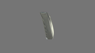
Invader Fractal

Invader Fractal in Mel version 1 Still some squares being left out, but all in all looking good.  version 2 Complete, but need to add more size variations
  version 4 variation 1 Rewrote most of the space filling portion, and added frames etc.
  variation 2
  variation 3 Based on Jared Tarbells Invader Fractal. except done in maya melscript. Below is the space filling portion of the script, using a main grid of 100x50 squares, we go through each one($j), if $j is white, j++, if not, search a random sized area for white squares, if a white square exists, we search random sized area - 1 for white squares and so on until random size = 1 and it must be black due to the first condition. If the random sized area have no white squares, we call the invader_plane()(not shown), which makes the invader plane at that area, and color that particular area white on the main_grid and continue(j++). There are two for loops within the main loop, L loop for going horizontal, which are increments of 50, and the K loop going vertical, which are increments of 1.
------------------------------------------------------------------------------------------------
 version 2 Complete, but need to add more size variations
  version 4 variation 1 Rewrote most of the space filling portion, and added frames etc.
  variation 2
  variation 3 Based on Jared Tarbells Invader Fractal. except done in maya melscript. Below is the space filling portion of the script, using a main grid of 100x50 squares, we go through each one($j), if $j is white, j++, if not, search a random sized area for white squares, if a white square exists, we search random sized area - 1 for white squares and so on until random size = 1 and it must be black due to the first condition. If the random sized area have no white squares, we call the invader_plane()(not shown), which makes the invader plane at that area, and color that particular area white on the main_grid and continue(j++). There are two for loops within the main loop, L loop for going horizontal, which are increments of 50, and the K loop going vertical, which are increments of 1.
 ------------------------------------------------------------------------------------------------
global proc main_method() {
 undoInfo -state off;
 global int $i;
 int $j, $k, $l, $ex;
 float $vtxPos[];
 string $xyz[];

 for($j = 0; $j < 5000; $j++) {

  print("START----------------------------------------\n");
  $ex = 0;
  select -cl;
  //int $j = 6;
  int $random_size = rand(1,11);
  hilite main_grid;
  for($l = ($random_size - 1) * 50; $l  >= 0; $l = $l - 50){
   string $bah[0] = `listSets -o main_grid.f[$j]`;
   $xyz[0] = $bah[0];
   if ($xyz[0] == "whiteShaderSG") {
  //  print("stopped immediately!!\n");
    $ex = 1;
    continue;
   }
   for ($k = $random_size - 1; $k >= 0; $k = $k - 1) {
    select -add ("main_grid.f[" + ($j+$k+$l) + "]");
    print("K LOOP  ");
    print("main_grid.f[" + ($j+$k+$l) + "]\n" + "$j=" + $j + " $k=" + $k + " $l=" + $l/50 + " size=" + $random_size + "\n");
    string $bah[0] = `listSets -o main_grid.f[($j + $k + $l)]`;
    if($bah[0] == "whiteShaderSG") {
  //   print("coord " + "random_size="  + $random_size + " k=" + $k + " l/50=" + ($l/50) + "\n"); //coordinate for white square
     int $dif;
     if($k > ($l/50)) {
      print("k larger");
      int $dif;
      for($dif = 0;$dif <= ($random_size - $l/50); $dif++) {
  //     print("dif=" + $dif + " random_size=" + $random_size + " k=" + $k + "\n");
       select -d ("main_grid.f[" + ($j+$k+$l+($dif*50)) + ":" + ($j+$k+$l+$random_size+($dif*50)) + "]");
      }
      for($dif = 0;$dif <= ($random_size - $k); $dif++) {
  //     print("dif=" + $dif + " random_size=" + $random_size + " k=" + $k + "\n");
       select -d ("main_grid.f[" + ($j + ($random_size - $dif) * 50) + ":" + ($j + $random_size + ($random_size - $dif) * 50) + "]");
      }
      $random_size = $k;
     }
     else if($k < ($l/50)) {
      print("l larger");
      $k = 0;
      select -cl;
      $random_size = $l/50;
     }
     else {
      select -cl;
      print("K is equal to L\n\n");
      $random_size = $k;
      $k = 0;
      break;
     }
    }
   }
  print(`ls -sl`);
  print("L LOOP   ");
  print("main_grid.f[" + ($j+$k+$l) + "]\n" + "$j=" + $j + " $k=" + $k + " $l=" + $l/50 + " size=" + $random_size + "\n\n");
  }
 if ($ex == 1) {
  continue;
 }
 hilite main_grid;
 sets -e -forceElement whiteShaderSG;
 print(`ls -sl`);
 polyChipOff -ch 0 -kft 1 -dup 1 -off 0 `ls -sl`;
 polySeparate -ch 0 -n temp main_gridShape;
 CenterPivot;
 move -r (($random_size/2)*(-1)) ($random_size/2) ($random_size/2) temp1.scalePivot temp1.rotatePivot;
 select temp temp1;
 parent -w;
 select -r main_grid;
 doDelete;
 rename "temp" "main_grid";
 float $vtxPos[3] = `xform -q -ws -t temp1.vtx[0]`;
 select -r temp1;
 doDelete;
 invader_plane;
 ls -sl;
 move -r $vtxPos[0] ($vtxPos[1]+1) $vtxPos[2];
 scale -r ($random_size) ($random_size) ($random_size);
 $i++;
 }
}
------------------------------------------------------------------------------------------------Tuesday, June 1, 2010
elevation matte
For example, the water line, where the side of a cliff/moutain/hill is washed off and exposes the mud/stone underneath. Or how snow appears at a certain altitude, or timber lines. You can use a measure distance tool to find the min max, and you can choose the coordinate system to find p. Usually world, or object.
Then connect to a spline.
point p = transform("object", P);
point maxp = point(0,max,0);
point minp = point(0,min,0);
point offsetp = point(0,offset,0);
result = (ycomp((p+offsetp)/(maxp-minp)));
Then connect to a spline.
Tuesday, May 18, 2010
substrate in rsl, version 3
Happy Mistakes. Not what i wanted, but at least it runs and gives me some interesting results.
 slbox source
 slbox source
Monday, May 10, 2010
Water droplets on surface
Water droplets on leafs.
Its a specular component with displaced shading normal. Some techniques demonstrated here are, 1. adding/modifying displaced shading normal 2. using the shape, and tile node to create the droplets and patterns 3. using shading normal to specify the angle where the droplets would fall away due to gravity.
-------------------------------------------------------------------------------------------------------------------- The tree branch of the specular component of the water droplet, remember, its just a component of the leaf surface.It consists of the spec(cook torrance), reflection, and refraction. None of it ray traced, but requires an hdri environment map, for this example, find a map thats green on the bottom, with cool fill light, and warm key.
--------------------------------------------------------------------------------------------------------------------
The tree branch of the specular component of the water droplet, remember, its just a component of the leaf surface.It consists of the spec(cook torrance), reflection, and refraction. None of it ray traced, but requires an hdri environment map, for this example, find a map thats green on the bottom, with cool fill light, and warm key.
-------------------------------------------------------------------------------------------------------------------- First let us define the shape and pattern of the droplet. We'll use a circle shape node, with a fuzz of 4. Connect to a float spline to define the profile of the droplet, as demonstrated on the left. Use a tile manifold node, where we can adjust the frequency and jitter, and under the manifold of tile, lets warp the ST a little to give it a more irregular look.
--------------------------------------------------------------------------------------------------------------------
First let us define the shape and pattern of the droplet. We'll use a circle shape node, with a fuzz of 4. Connect to a float spline to define the profile of the droplet, as demonstrated on the left. Use a tile manifold node, where we can adjust the frequency and jitter, and under the manifold of tile, lets warp the ST a little to give it a more irregular look.
-------------------------------------------------------------------------------------------------------------------- I also multiply the above with this function, which is that every point thats flat or less than x angle is white, while everything thats steep and greater than x angle is black. Using the dot product between the vector that points in the world y direction and the normal, we get the cosine of the angle.
--------------------------------------------------------------------------------------------------------------------
I also multiply the above with this function, which is that every point thats flat or less than x angle is white, while everything thats steep and greater than x angle is black. Using the dot product between the vector that points in the world y direction and the normal, we get the cosine of the angle.
-------------------------------------------------------------------------------------------------------------------- The key to the droplet is here, we displace the point on surface for this specular component by adding the above to p.
--------------------------------------------------------------------------------------------------------------------
The rest is pretty straightforward, be sure to mask out the droplet on both the refraction and
spec. I also connected "diffuse>colortogray" to the refraction intensity to control the shadow side of the leaf droplet. Otherwise it'll be too bright, on further thought, I probably should do the same to the spec component as a precautionary measure.
The key to the droplet is here, we displace the point on surface for this specular component by adding the above to p.
--------------------------------------------------------------------------------------------------------------------
The rest is pretty straightforward, be sure to mask out the droplet on both the refraction and
spec. I also connected "diffuse>colortogray" to the refraction intensity to control the shadow side of the leaf droplet. Otherwise it'll be too bright, on further thought, I probably should do the same to the spec component as a precautionary measure.
 --------------------------------------------------------------------------------------------------------------------
Note 1: One problem I have encountered is when the leafs are animated, the angle cut off is too sharp, one possible solution is simply to bake in the position of the droplets into a texture. Anything more complex, for example, droplet falling off the leaf would be better dealt with in FX.
--------------------------------------------------------------------------------------------------------------------
Note 1: One problem I have encountered is when the leafs are animated, the angle cut off is too sharp, one possible solution is simply to bake in the position of the droplets into a texture. Anything more complex, for example, droplet falling off the leaf would be better dealt with in FX.
 The tree branch of the specular component of the water droplet, remember, its just a component of the leaf surface.It consists of the spec(cook torrance), reflection, and refraction. None of it ray traced, but requires an hdri environment map, for this example, find a map thats green on the bottom, with cool fill light, and warm key.
--------------------------------------------------------------------------------------------------------------------
The tree branch of the specular component of the water droplet, remember, its just a component of the leaf surface.It consists of the spec(cook torrance), reflection, and refraction. None of it ray traced, but requires an hdri environment map, for this example, find a map thats green on the bottom, with cool fill light, and warm key.
-------------------------------------------------------------------------------------------------------------------- First let us define the shape and pattern of the droplet. We'll use a circle shape node, with a fuzz of 4. Connect to a float spline to define the profile of the droplet, as demonstrated on the left. Use a tile manifold node, where we can adjust the frequency and jitter, and under the manifold of tile, lets warp the ST a little to give it a more irregular look.
--------------------------------------------------------------------------------------------------------------------
First let us define the shape and pattern of the droplet. We'll use a circle shape node, with a fuzz of 4. Connect to a float spline to define the profile of the droplet, as demonstrated on the left. Use a tile manifold node, where we can adjust the frequency and jitter, and under the manifold of tile, lets warp the ST a little to give it a more irregular look.
-------------------------------------------------------------------------------------------------------------------- I also multiply the above with this function, which is that every point thats flat or less than x angle is white, while everything thats steep and greater than x angle is black. Using the dot product between the vector that points in the world y direction and the normal, we get the cosine of the angle.
--------------------------------------------------------------------------------------------------------------------
I also multiply the above with this function, which is that every point thats flat or less than x angle is white, while everything thats steep and greater than x angle is black. Using the dot product between the vector that points in the world y direction and the normal, we get the cosine of the angle.
--------------------------------------------------------------------------------------------------------------------
 --------------------------------------------------------------------------------------------------------------------
Note 1: One problem I have encountered is when the leafs are animated, the angle cut off is too sharp, one possible solution is simply to bake in the position of the droplets into a texture. Anything more complex, for example, droplet falling off the leaf would be better dealt with in FX.
--------------------------------------------------------------------------------------------------------------------
Note 1: One problem I have encountered is when the leafs are animated, the angle cut off is too sharp, one possible solution is simply to bake in the position of the droplets into a texture. Anything more complex, for example, droplet falling off the leaf would be better dealt with in FX.
Tuesday, May 4, 2010
substrate in rsl, version 2
 one main branch to the left, with branching to the right at every point on the main branch. Need to add branching at EVERY iteration.
 result = 0;
point stspace = point((scale*s)+offset,(scale*(1-t))+offset,0);
uniform float i,j;
float x[100],y[100],x1[100],y1[100],dx,dy,dx1,dy1,line[100],line1[100],defuzz,newlength,dist,dist1;
point p[100],p1[100];
defuzz = 0;
//initialize first variables
x[0] = vx1;
x[1] = vx2;
y[0] = vy1;
y[1] = vy2;
p[0] = point(x[0],y[0],0);
p[1] = point(x[1],y[1],0);
line[0] = ptlined(p[0],p[1],stspace);
j = 0;
for (i = 1; i <= 1; i += 1) {
newlength = cellnoise(i)/2;
dx = x[i]-x[i-1];
dy = y[i]-y[i-1];
dist = sqrt(pow(dx,2)+pow(dy,2));
dx /= dist; dy /= dist; //perpendicular points, left
x[i+1] = x[i] - (newlength/2)*dy;
y[i+1] = y[i] + (newlength/2)*dx;
p[i+1] = point(x[i+1],y[i+1],0);
line[i] = ptlined(p[i],p[i+1],stspace);
defuzz += 1-smoothstep(width-fuzz,width+fuzz,line[i]);
for (j = 1; j <= 5; j += 1) {
newlength = cellnoise(j*i)/2;
x1[0] = x[i-1];
x1[1] = x[i];
y1[0] = y[i-1];
y1[1] = y[i];
p1[0] = point(x1[0],y1[0],0);
p1[1] = point(x1[1],y1[1],0);
dx1 = x1[j]-x1[j-1];
dy1 = y1[j]-y1[j-1];
dist1 = sqrt(pow(dx1,2)+pow(dy1,2));
dx1 /= dist1;
dy1 /= dist1; //perpendicular points, left
x1[j+1] = x1[j] + (newlength/2)*dy1;
y1[j+1] = y1[j] - (newlength/2)*dx1;
p1[j+1] = point(x1[j+1],y1[j+1],0);
line1[j] = ptlined(p1[j],p1[j+1],stspace);
defuzz += 1-smoothstep(width-fuzz,width+fuzz,line1[j]);
}
}
result = defuzz;
Monday, May 3, 2010
substrate in rsl, version 1

result = 0;
point stspace = point((scale*s)+offset,(scale*(1-t))+offset,0);
uniform float i;
float x[100],y[100],dx,dy,line[100],defuzz,newlength,dist;
point p[100];
defuzz = 0;
//initialize first variables
x[0] = x1;
x[1] = x2;
y[0] = y1;
y[1] = y2;
p[0] = point(x[0],y[0],0);
p[1] = point(x[1],y[1],0);
line[0] = ptlined(p[0],p[1],stspace);

for (i = 1; i <= 98; i += 1) {
 newlength = cellnoise(i);

 dx = x[i]-x[i-1];
 dy = y[i]-y[i-1];
 dist = sqrt(pow(dx,2)+pow(dy,2));
 dx /= dist;
 dy /= dist;

 //perpendicular points, left and right
 x[i+1] = x[i] - (newlength/2)*dy;
 y[i+1] = y[i] + (newlength/2)*dx;
 p[i+1] = point(x[i+1],y[i+1],0);

 line[0] = ptlined(p[0],p[1],stspace);
 line[i] = ptlined(p[i],p[i+1],stspace);
 defuzz += 1-smoothstep(width-fuzz,width+fuzz,line[i]);
 result = defuzz;
 }
Thursday, April 29, 2010
random snippets 01

result = 0;
point stspace = point((scale*s)+offset,(scale*(1-t))+offset,0);
float i;
float x[100],y[100],line[100],defuzz[100];
point p[100]; p[0] = point(.2,.6,0);
for (i=0;i<100;i+=1) {
 x[i] = 2*noise(.5+i);
 y[i] = 2*noise(.5+i+13);     p[i] = point(x[i],y[i],0);
 line[i] = ptlined(p[i],p[i-1],stspace);
 defuzz[i] = 1-smoothstep(width-fuzz,width+fuzz,line[i]);
 result += defuzz[i];
 }
Tuesday, April 20, 2010
desaturating individual color components

result = 0;
float r = comp(v1,0);
float g = comp(v1,1);
float b = comp(v1,2);
float lumr = .2125*comp(v1,0);
float lumg = .7154*comp(v1,1);
float lumb = .0721*comp(v1,2);
color desatr = mix(color(lumr), color(r,0,0), saturationr);
color desatg = mix(color(lumg), color(0,g,0), saturationg);
color desatb = mix(color(lumb), color(0,0,b), saturationb);
result = desatr+desatg+desatb;
Friday, April 16, 2010
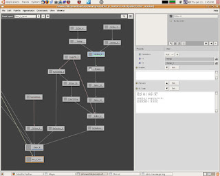
Graphearea, color coding shaders
 laying out a typical shader. In this example is a character with clothes and some accessories. The blue nodes are AOV nodes(as in bluescreen mattes, get it?), the green nodes are control mattes. The red nodes are global control nodes, occ. Yellow are ensembles, and purple are unused. If there's a way to define our own custom colors, please share.
Wednesday, April 7, 2010
shading normals
straight from Renderman pro server documentation,
with some errors in the above code, we can use this in a vector slbox to slightly alter the shading normal which we can then plug into a shading component(specular and reflection). say we want to break up the specular reflection of specular to make it look like water droplets on skin. we use the above code, use a fractal for "a", create our own point p and normal n, and normalize the final n. It'll look like this,
The addition of point "shader" (0,0,0) in the second line accounts for the fact that N is really a vector (or normal), and thus should not transform in the same way as a point.
This is the old way of transforming vectors and normals. These days, we encourage you to use the following equivalent (but less confusing and cheaper!) construct:
normal Nsh; Nsh = ntransform ("shader", N); For vectors (as opposed to normals), one should use the vtransform function.
P += normalize(N) * a * amplitude;t a;
P = transform("object", P);
N = transform("object", N + point "object" (0,0,0));
P = transform("object", "current", P);
N = calculatenormal(P);
with some errors in the above code, we can use this in a vector slbox to slightly alter the shading normal which we can then plug into a shading component(specular and reflection). say we want to break up the specular reflection of specular to make it look like water droplets on skin. we use the above code, use a fractal for "a", create our own point p and normal n, and normalize the final n. It'll look like this,
point p = transform("object", P);
normal n = transform("object", N + point "object" (0,0,0));
p += normalize(n) * a * amplitude;
p = transform("object", "current", p);
n = calculatenormal(p);
result = normalize(n);
The addition of point "shader" (0,0,0) in the second line accounts for the fact that N is really a vector (or normal), and thus should not transform in the same way as a point.
This is the old way of transforming vectors and normals. These days, we encourage you to use the following equivalent (but less confusing and cheaper!) construct:
normal Nsh; Nsh = ntransform ("shader", N); For vectors (as opposed to normals), one should use the vtransform function.
Thursday, March 25, 2010
Cleaning graph layouts
When working in slim and using an auto maya shading group > slim script, slim will generate a graph layout for every node. For me, I like to work with a single graph layout, like in Shake. You could delete the layouts one by one, or you can read on, it'll be slightly different what with all the different pipelines.
Here's my workflow,
1. reference the rigging file
2. save as rig.ma
3. export the maya shaders into slim, it'll generate all the necessary connections, textures > diffuse > delux > ensemble, and a billion layouts.
4. in slim, select all your nodes, thus grouping all the nodes into one graph, and rename the graph to "all"
5. export your slim palette, our company has an auto export script which will export the palette, the attach mel, the meta file, and the aov all at once. If not, you'll have to manually do this part.
6. find your palette, open with text editor, search for layouts, it look something like this,
graphlayouts {
layout Diffuse_layout {
arrangemethod auto
roots 1400_DXwEjq30000
traversemethod upstream
scroll {{} {}}
transforms {1 {0 0}}
}
7. delete all the layouts between graphlayout {} except the one you made, "all".
8. save. open rig.ma, attach the palette.
Friday, March 12, 2010
texture, object, uniform mattes
define AOVs by specifying primvars with the correct type. uniform if its the same color throughout the surface, ie holdout mattes varying if it has different colors through the surface.
primvars
sl
To specify per object mattes would be to use attribute() and match() functions to assign colors to groups or single objects. For example,
sl
So, the above code writes to two mattes, cubes and cones, in which cubeShape10 will be red and cubeShape20 will be green in matte_cubes.
primvars
output varying color matte_name;
sl
extern color matte_name = v1;
result = 0;
To specify per object mattes would be to use attribute() and match() functions to assign colors to groups or single objects. For example,
sl
string xxoo; attribute("identifier:name", xxoo);
if (match("cubeShape10",xxoo))
    extern color matte_cubes = color(r,0,0);
else if (match("cubeShape20", xxoo))
    extern color matte_cubes = color(0,g,0);
else if (match("coneShape30",xxoo))
    extern color matte_cones = color(r,0,0);
So, the above code writes to two mattes, cubes and cones, in which cubeShape10 will be red and cubeShape20 will be green in matte_cubes.
Saturday, February 6, 2010
overriding displacment
sometimes you don't want the specular or reflection component to be affected by bump/displacement, create a vector slbox and plug into the normal of the component
normal nn;
displacement("__Norig",nn);
result = normalize(nn);
Wednesday, February 3, 2010
set SSS bake shading rate
this is for use with sss bake, it sets the bake shading rate to 1 if its less than 0.1, and multiplies it by 5. In most cases, it just means a shading rate of 5.
[ set bakeLevel 5;
set oriShadingRate [mel "mtor control getvalue -rg shadingRate"]
if { $oriShadingRate < 0.1 } { set oriShadingRate 1.0 }
set newShadingRate [expr $oriShadingRate * $bakeLevel ]
if (\$CONTEXT=="BAKECONTEXT") { return "ShadingRate $newShadingRate" }
Thursday, January 28, 2010
building a zdepth shader tree
ingredients,
1. sampler info
2. set range
3. blender
1. connect point camera Z of sampler info to value x of set range.
2. set min/max to 0 and 1, and set old min to distance between camera and furthest point in scene. for example -1000.
3. connect out value x to blender.blender
output the color.
Tuesday, January 19, 2010
desaturating
find the luminance, by separating out the components first, multiply each of the component with luma coefficients(ITUR Rec. 709 ) for RGB respectively. Add them up and mix original image with desaturated image with a matte, in this case a float.
float red = comp(v1,0);
float green = comp(v1,0);
float blue = comp(v1,0);
float luma = .2125*comp(v1, 0) + .7154*comp(v1, 1) + .0721*comp(v1, 2);
result = mix(color(luma),v1,1-v2);
Monday, January 18, 2010
Faking Parallax
Faking parallax is one trick i've learned in videogame texturing, its applicable in non-videogame surfacing as long as it is used in the mid to far background.


 The bulb inside this headlight is created using the above technique, as we turn and look from the side, the bulb will become occluded, achieving a small sense of depth.
 The basic concept is to take the camera normal and use it to offset the UV
normal Ns = normalize(transform("camera", N));
float x = xcomp(Ns);
float y = ycomp(Ns);
float z = zcomp(Ns);
result = x;
the above code is like facing direction, but only in the x direction, make another one for y. Invert y, set a new min/max with remap. The input min/max should be -1 to 1 and the new min/max should be something less than +/-0.25, depends on your texture and how much shift you want. Connect to a manifold slbox with the following snippet,
float ss = s+v3;
float tt = t+v4;
result_Q = point(ss,tt,0);
result_dQu = (0,0,0);
result_dQv = (0,0,0);
where v3 and v4 are the x and y from above.
and then connect to your textures/shapes ST.
You can do this in maya as well, just connect the camera normal from sampler info to uv offset of a place2d node. With a setrange in between, something like that, out of the top of my head.
The basic concept is to take the camera normal and use it to offset the UV
normal Ns = normalize(transform("camera", N));
float x = xcomp(Ns);
float y = ycomp(Ns);
float z = zcomp(Ns);
result = x;
the above code is like facing direction, but only in the x direction, make another one for y. Invert y, set a new min/max with remap. The input min/max should be -1 to 1 and the new min/max should be something less than +/-0.25, depends on your texture and how much shift you want. Connect to a manifold slbox with the following snippet,
float ss = s+v3;
float tt = t+v4;
result_Q = point(ss,tt,0);
result_dQu = (0,0,0);
result_dQv = (0,0,0);
where v3 and v4 are the x and y from above.
and then connect to your textures/shapes ST.
You can do this in maya as well, just connect the camera normal from sampler info to uv offset of a place2d node. With a setrange in between, something like that, out of the top of my head.
Monday, January 4, 2010
Using packages in SLIM to create an RGB splitter
This create a small package that splits colors to RGB or just three outputs with some simple contrast controls.
1. Import a gammaimage

 2. create 3 color slbox and add a color v1 to each of them and add the following code
color red = comp(v1,0);
result = red;
duplicate the code to green and blue substituting 0 with 1 and 2 respectively.
3. create a float spline, and rename the first knot to low, and last knot to high.
4. duplicate the spline and rename the spline to each color. ie red_spline
5. shift select the SLBOX nodes in order of R then G then B. and select the splines in order as well.
6. Right click and click on package.
7. open the package, select red_spline, publish basis, low, p0, high, p1. Do the same for GB.
8. close the package.
This package takes three inputs and has simple contrast controls, it would be great if someone can add the float spline GUI inside the package.
2. create 3 color slbox and add a color v1 to each of them and add the following code
color red = comp(v1,0);
result = red;
duplicate the code to green and blue substituting 0 with 1 and 2 respectively.
3. create a float spline, and rename the first knot to low, and last knot to high.
4. duplicate the spline and rename the spline to each color. ie red_spline
5. shift select the SLBOX nodes in order of R then G then B. and select the splines in order as well.
6. Right click and click on package.
7. open the package, select red_spline, publish basis, low, p0, high, p1. Do the same for GB.
8. close the package.
This package takes three inputs and has simple contrast controls, it would be great if someone can add the float spline GUI inside the package.
Subscribe to:
Posts (Atom)