Showing posts with label slim. Show all posts

Wednesday, April 25, 2012

Character Shaders and Controlling SSS in Renderman/Slim

Introduction
Haven't updated this blog in a while, thought i need to write some of these down in case
I forget. So... how to control SSS? What kind of control is expected? The default controls given in APSubsurfacescattering looks like this,

APSubsurfacescattering
Your basic, intensity, incolor, outcolor, albedo, path length etc etc. Quite a few, which is enough for most shaders. And you can add multiple layers of SSS for a desired effect. Now, lets take a look at my shader trees in Slim.

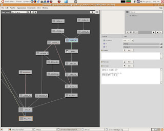
Complete Shading Graph of a Single Character


In Depth
The yellow nodes are Allpurpose nodes, the red are shading components, and the purple nodes are global controls. The graph looks like this mainly because this is a single character with multiple  shading groups. Most of them are the same shader, but different textures. The three trees to the right are different shaders, mouth, teeth, tongue. So lets just take a look at a single tree.


Here we can see more clearly the structure of a shader. Not much really, spec and rim are shared across all the other shaders, diffuse has its own textures, incandescence is used in our pipeline as an automatic AOV output. SSS here is called APMultiSSS, its a template written by our shader TD that combines three SSS nodes into one, its the same as making SSS nodes and layering the colors together. The purple controls are neccessary as I don't want to change 5 shaders everytime I want to tweak it. Now, let me explain the SSS controls that were needed, the material for this character is ceramic, so there shouldn't be a lot of SSS, yet a strong contrasty look is to be avoided. So, what this means in the end is, strong front scatter to have a soft look, weak back scatter to avoid a translucense effect. To achieve this,  we will need two SSS nodes with specific controls. Lets take a look at the SLBOXs in this shader tree,

Front scatter control

v1 is the diffuse texture image
v2 is control float
sat is control float, 1 for full saturation 0 for black and white
v5 is a matte to separate non-SSS parts of the model

The first part is to make a control like the saturation control in the Adjust node. The second part, in the if statement, is to make sure that every point pointing AWAY from the camera will retrun 0. Every point pointing TOWARD the camera will return some value, which in this case, is used as the incolor of the SSS shader.

The result = desat*v2*v6, is thus simply that the incolor is a desaturated color texture, multiply by intensity(which was 3), and multiplied by a matte which blacks out areas that doesn't need SSS. So, finally, for this part, the shader, the output is a high intensity SSS shader when the light and camera is in the same general direction, but have no SSS when the light and the camera is opposite each other(light behind object). 

Back scatter control
The back SSS control is just the reverse of the above node, every point pointing away the camera has an intensity of v1*v2, which is the original color matted out by v2. And every point pointing towards the camera has a value of 0.

Conclusion
And that is it. Its pretty much just using an If statement to to control the behavior of what happens when a point is pointing toward the camera or when the point is pointing away from the camera

Wednesday, October 19, 2011

Scaling Normal Maps in Slim

v1 is the normal map input.
v2 is our multiplier

1. get individual channels first
float red = comp(v1,0);

2. since normal maps have R and G values ranged between 0.5 and 1 lets subtract 0.5 from it so that it ranges from 0 to 0.5
float red1 = red - 0.5

3. multiply red1 with v2 to scale our red and green values and then add 0.5 to have our range back at 0.5 to 1

result = (red1*v2)+0.5;


float red = comp(v1,0)-0.5;
float green = comp(v1,1)-0.5;
float red1 = (red*v2)+0.5;
float green1= (green*v2)+0.5;
result = color(red1,green1,1);


Monday, May 10, 2010

Water droplets on surface

Water droplets on leafs. Its a specular component with displaced shading normal. Some techniques demonstrated here are, 1. adding/modifying displaced shading normal 2. using the shape, and tile node to create the droplets and patterns 3. using shading normal to specify the angle where the droplets would fall away due to gravity. --------------------------------------------------------------------------------------------------------------------
The tree branch of the specular component of the water droplet, remember, its just a component of the leaf surface.It consists of the spec(cook torrance), reflection, and refraction. None of it ray traced, but requires an hdri environment map, for this example, find a map thats green on the bottom, with cool fill light, and warm key. --------------------------------------------------------------------------------------------------------------------
First let us define the shape and pattern of the droplet. We'll use a circle shape node, with a fuzz of 4. Connect to a float spline to define the profile of the droplet, as demonstrated on the left. Use a tile manifold node, where we can adjust the frequency and jitter, and under the manifold of tile, lets warp the ST a little to give it a more irregular look. --------------------------------------------------------------------------------------------------------------------
I also multiply the above with this function, which is that every point thats flat or less than x angle is white, while everything thats steep and greater than x angle is black. Using the dot product between the vector that points in the world y direction and the normal, we get the cosine of the angle. --------------------------------------------------------------------------------------------------------------------
The key to the droplet is here, we displace the point on surface for this specular component by adding the above to p. -------------------------------------------------------------------------------------------------------------------- The rest is pretty straightforward, be sure to mask out the droplet on both the refraction and spec. I also connected "diffuse>colortogray" to the refraction intensity to control the shadow side of the leaf droplet. Otherwise it'll be too bright, on further thought, I probably should do the same to the spec component as a precautionary measure. -------------------------------------------------------------------------------------------------------------------- Note 1: One problem I have encountered is when the leafs are animated, the angle cut off is too sharp, one possible solution is simply to bake in the position of the droplets into a texture. Anything more complex, for example, droplet falling off the leaf would be better dealt with in FX.

Thursday, April 29, 2010

random snippets 01


result = 0;
point stspace = point((scale*s)+offset,(scale*(1-t))+offset,0);
float i;
float x[100],y[100],line[100],defuzz[100];
point p[100]; p[0] = point(.2,.6,0);
for (i=0;i<100;i+=1) {
 x[i] = 2*noise(.5+i);
 y[i] = 2*noise(.5+i+13);     p[i] = point(x[i],y[i],0);
 line[i] = ptlined(p[i],p[i-1],stspace);
 defuzz[i] = 1-smoothstep(width-fuzz,width+fuzz,line[i]);
 result += defuzz[i];
 }

Tuesday, April 20, 2010

desaturating individual color components


result = 0;
float r = comp(v1,0); 
float g = comp(v1,1); 
float b = comp(v1,2);
float lumr = .2125*comp(v1,0);
float lumg = .7154*comp(v1,1);
float lumb = .0721*comp(v1,2);
color desatr = mix(color(lumr), color(r,0,0), saturationr);
color desatg = mix(color(lumg), color(0,g,0), saturationg);
color desatb = mix(color(lumb), color(0,0,b), saturationb);
result = desatr+desatg+desatb;

Friday, March 12, 2010

texture, object, uniform mattes

define AOVs by specifying primvars with the correct type. uniform if its the same color throughout the surface, ie holdout mattes varying if it has different colors through the surface.


primvars


output varying color matte_name;  


sl
extern color matte_name = v1;
result = 0; 


To specify per object mattes would be to use attribute() and match() functions to assign colors to groups or single objects. For example,


sl


string xxoo; attribute("identifier:name", xxoo); 
if (match("cubeShape10",xxoo)) 
    extern color matte_cubes = color(r,0,0);
else if (match("cubeShape20", xxoo)) 
    extern color matte_cubes = color(0,g,0); 
else if (match("coneShape30",xxoo)) 
    extern color matte_cones = color(r,0,0);


 So, the above code writes to two mattes, cubes and cones, in which cubeShape10 will be red and cubeShape20 will be green in matte_cubes.

Saturday, February 6, 2010

overriding displacment

sometimes you don't want the specular or reflection component to be affected by bump/displacement, create a vector slbox and plug into the normal of the component normal nn; displacement("__Norig",nn); result = normalize(nn);

Tuesday, January 19, 2010

desaturating

find the luminance, by separating out the components first, multiply each of the component with luma coefficients(ITUR Rec. 709 ) for RGB respectively. Add them up and mix original image with desaturated image with a matte, in this case a float. float red = comp(v1,0); float green = comp(v1,0); float blue = comp(v1,0); float luma = .2125*comp(v1, 0) + .7154*comp(v1, 1) + .0721*comp(v1, 2); result = mix(color(luma),v1,1-v2);

Monday, January 18, 2010

Faking Parallax

Faking parallax is one trick i've learned in videogame texturing, its applicable in non-videogame surfacing as long as it is used in the mid to far background. The bulb inside this headlight is created using the above technique, as we turn and look from the side, the bulb will become occluded, achieving a small sense of depth. The basic concept is to take the camera normal and use it to offset the UV normal Ns = normalize(transform("camera", N)); float x = xcomp(Ns); float y = ycomp(Ns); float z = zcomp(Ns); result = x; the above code is like facing direction, but only in the x direction, make another one for y. Invert y, set a new min/max with remap. The input min/max should be -1 to 1 and the new min/max should be something less than +/-0.25, depends on your texture and how much shift you want. Connect to a manifold slbox with the following snippet, float ss = s+v3; float tt = t+v4; result_Q = point(ss,tt,0); result_dQu = (0,0,0); result_dQv = (0,0,0); where v3 and v4 are the x and y from above. and then connect to your textures/shapes ST. You can do this in maya as well, just connect the camera normal from sampler info to uv offset of a place2d node. With a setrange in between, something like that, out of the top of my head.