Showing posts with label mental ray. Show all posts

Monday, January 27, 2014

Writing mental ray shaders: Simplest Diffuse!

Intro 

Back to the basics. The function for lambertian reflectance is


source: wikipedia
Basically, final result equals the dot product of light normal(L) and surface normal(N), multiply by diffuse color(C), multiply by color of light(IL). I'll write the simplest diffuse shader that doesn't get into light loops and getting light information. 


MI Source

declare shader
 color "jc_simple_diffuse" (
  color "diffuse" default 1 1 1,
  vector "light_dir" default 0 0 0)
 version 1
 apply material
end declare

C Source


#include "shader.h"

DLLEXPORT

struct jc_simple_diffuse {
 miColor diffuse;
 miVector lightdir;
 };

DLLEXPORT

int jc_simple_diffuse_version(void) {return(1);}

DLLEXPORT

miBoolean jc_simple_diffuse(
 miColor *result,
 miState *state,
 struct jc_simple_diffuse *params) {

 miScalar dot_nl;

 miColor *diff = mi_eval_color(&params->diffuse);
 miVector *dir = mi_eval_vector(&params->lightdir);
 dot_nl = -mi_vector_dot(&state->normal, dir);
 result->r = diff->r * dot_nl;
 result->g = diff->g * dot_nl;
 result->b = diff->b * dot_nl;
 result->a = 1.0;
 
 return(miTRUE);
 }

Conclusions

The only inputs are diffuse color and a light vector. Inputing -1 -1 -1 in light direction gives it a light looking like in fig 1.
Fig 1: simple diffuse

Fig 2: simple diffuse attribute editor
Since light dir is expressed as vectors, by connecting transforms of x, y, z to Light Dir we can change the light direction of this particular diffuse shader.

Fig 3: demo 01
In fig 3, I connected the translation of xyz of a cube to the light dir, as well as created a direction light and aim constraint it to the cube to better illustrate. When I move the cube.z to 1, the light points left.

Fig 4: demo 02
In fig 4, when i move the cube.z to 5, the falloff becomes really harsh. This is due to dot product of the surface normal and light dir becoming smaller and smaller as the light dir moves further away.

Fig 5: demo 03
In fig 5, basic 45 degree angle light. Harsh falloff could be fixed by normalizing light dir to unit vectors.


Monday, October 8, 2012

MentalRay Custom Color Buffer / Linear Work Flow

Goal
Convert an existing mental ray shaded object into comp passes.

Introduction


Pic 1

In pic 1, we have the original shader.


Pic 2

In pic 2, we have the shader network. The top blinn is for the wooden base, the bottom material is for the porcelein/ceramic material. It consists of a fast_SSS connected to a mia_material, the color correction is to vary the front SSS color from the back SSS color.


Seperating the Passes
To reiterate, the goal is to recreate Pic 1 from passes.

Step 1: Create Passes
First lets go into Render Settings > Passes


Pic 3: Passes Window


Click on the first button on the right. It'll show a window with a list of different available passes. We'll just click on custom color, there are options to enter a prefix if needed. Rename the pass as "Diffuse". Do this another 3 times and name it as, "Refl", "SSS", "Spec". Once created, select all the passes and press the green check button in the middle of the Passes window. This will activate the passes.

Step 2: Rebuild the Shader Network
Lets do the wooden base shader first. This is simple blinn shader that consists of diffuse, specularity, and reflectivity.

Step 2A: Base Section
1. So let us create 3 writeToColorBuffer nodes in the hypershade. It can be found under the hypershade>create>mental ray>miscellaneous. Rename them as diffuse, spec, and refl. The custom color drop down list will contain a list of color passes we created in Step 1. Select the corresponding color passes for each writeToColorBuffer node.

2. Let us duplicate the blinn shader as well, since we can't output individual shading components from the blinn shader, we will need to re-create the shading components.


  • Diffuse: For the original blinn, turn reflectivity to 0 and specular color to black, and rename it diffuse.
  • Reflection: For reflection, create a mib_reflect under Sample Compositing
  • Specular: For the duplicated blinn, change diffuse to black and reflectivity to 0 and rename it to spec.


3. Now connect each of the blinn shader output to their corresponding writeToColorBuffer input. If you select all the nodes and graph it now, it'll show the pass nodes in the hypershade as well, as shown in pic 4.


Pic 4


4. If you render now, only the diffuse pass will show up since only the diffuse shader is connected to a shading group. One way for the other writeToBuffer node to evaluate is have the blinn somehow connect to the shadingGroup. But the official method is to use the evaluation passthrough of each writeToBuffer node.

  • Connect the refl node to the spec node, and the spec node to the diffuse node.
  • Disconnec the diffuse shader from the shading group
  • Create a surface shader and connect it to the shading group
  • Connect the diffuse writeToBuffer node to the surface shader input color.

It'll look something like in pic 5.


Pic 5


5. If we render now, it'll look like this,


Pic 6

The base will be black because of the surface shader. Here is what the passes look like,


Diffuse


Reflection


Specular


This concludes the base part.

Step 2B: Vase Section


  1. Create a SSS pass in render settings
  2. Create 4 writeToColorBuffer nodes and rename them as 2XSSS, refl, diffuse
  3. Upgrade the shaders,the vase part, I have a misss_fast_shader for diffuse and SSS, and a mia_material for the reflection. The misss shader is connected to the mia_material through additional colors. However, it would not matter once we use passes. These shaders are much easier to ouput passes since you can upgrade them to their respective X_passes shaders. The connections will be a little messed up but its easy to fix.
  4. Once upgraded, have the misss output front and back SSS results into to color buffers.
  5. Output diffuse result into the diffuse color buffer
  6. Output the reflection result from mia_material into the refl color buffer
  7. Disconnect materials from the shading group
  8. Create a surface shader and connect the last buffer node to the surface shader


pic 7
The final layout. 

Step 3: Render
Diffuse

Reflection

Specular

SSS
Combining the Passes
Once combined, you will notice that the combined passes will NOT look like the master beauty pass, this is due to the exposure mental ray adds to the beauty pass that is not added to the buffers. 

Comped Image

Master Beauty


To correct for this, we will need to upgrade our workflow to linear workflow.

Linear Workflow


  1. Change render settings > file format to exr
  2. Change render settings > quality > framebuffer to 4x16bit half in render settings
  3. Change render view > display > 32bit HDR
  4. Change render > display > color management, image color profile to linear, and display color profile to sRGB
  5. Color correct ALL texture/color swatch with a gamma correct node set to 0.4545


Comped Image

Master Beauty

The final shader network looks like this,


Final Shader Network

To have both master beauty and final passes rendered out, I connect the last outEvaluation to outMatteOpacity of the surface shader, doesn't effect anything but it will let it evaluate the passes. 

Notes I
There are limitations to custom color buffer workflow, some shading components from maya shaders will not output correctly and some might even interfere with other shading components. The safest way to ensure a consistent workflow would be to stick with mental ray shaders and keep it simple, after all, we're pretty much offloading the light tweak stage to the compositing department in this workflow.

Notes II
To improve the workflow it is advisable to standardize/limit the shaders used and also automate the pass and gamma correction process. Mel scripts will be provided.... when i get around to it.


Monday, April 25, 2011

Architectural Visualization: Planks

Intro
Since I'll be working on a architectural visualization project, I will document the techniques I found interesting. The first notable one so far are the planks near a pool area.

For the planks, I found an 1kx1k tileable image. With some scripting and hypershade trickery, it is more than enough, even at closeups.

Goal
1. add transform noise to the planks
2. offset UV of individual planks
3. add different values to the planks

Sunday, April 17, 2011

Writing mental ray shaders: UV Chooser

Intro
Here is a shader that loads a texture, and chooses which UV set to use. There's an equivalent node in Maya, but it requires setting the input values in hypershade, which isn't intuitive for the avg user. In 3ds max the same thing is set with UV channels. Multi texture layering is an important technique when dealing repetitive textures, by using 5 1k textures, i can create a better looking texture than a single 5k texture. Not sure why maya is making it so hard for avg users.

MI Source
declare shader
 color "uv_chooser" (
  color texture "tex",
  integer "uv_sets"
 )
apply material
end declare


C Source
#include "shader.h"

struct uv_chooser{
 miTag tex;
 miInteger uv_sets;
 };

miBoolean uv_chooser(miColor *result, miState *state, struct uv_chooser *params) {
 miTag tex = *mi_eval_tag(&params->tex);
 miInteger uv_sets = *mi_eval_integer(&params->uv_sets);
 int i = uv_sets;
 mi_lookup_color_texture(result, state, tex, &state->tex_list[i]);
 return miTRUE;
 }


Friday, April 15, 2011

Writing mental ray shaders: Mosaic Tiles

Introduction
Here is a little something thats detours from the book. Combining quantization and texture uv, I can create a mosaic effect. 

Methodology
1. Have an input texture
2. quantize the uv_coordinates
3. use the quantized_uv_coordinates inside mi_lookup_texture_color

From top to bottom: Original, tile = 20, tile = 10, Porn?!

Writing mental ray shaders: Texture Mapping

Introduction
Once we have UV coordinates, we can start mapping textures according to these coordinates. This section will introduce the use of miTAG, and the function mi_lookup_color_texture(). I'll create a node thats similar in function to the 2d_placement node in Maya. Key functions are, UV offsets, and  UV scaling.


Notes
Name
Arguments
Comments
mi_lookup_color_texture
*col, *state, tag, *v
Return the value in a color texture at a given coordinate.

The tag is assumed to be a texture as taken from a color texture parameter of a shader. This function checks whether the tag refers to a shader (procedural texture) or an image (file texture or byte stream), depending on which type of color texture statement was used in the .mi file. If tag is a shader, coord is stored in state→tex, the referenced texture shader is called, and its return value is returned. If tag is an image, coord is brought into the range (0…1, 0…1) by removing the integer part, the image is looked up at the resulting 2D coordinate, and miTRUE is returned. If the texture has been marked for filtering, like with the filter keyword in the .mi file, then multi-level pyramid filtering is performed, a procedure derived from classical mip-map textures. In both cases, the color resulting from the lookup is stored in *color.

Thursday, April 14, 2011

Writing mental ray shaders: Quantization Part II

Intro
Here I will combine my two previous posts into one shader, the uv_as_colors_banding shader. I'll implement the rounding function as demonstrated in the wikipedia article. I did not understand some of the source code from the book

Methodology
1. Implement uv as colors
2. Define u_count, which is the amount of banding in the u direction
3. Define v_count, which is the amount of banding in the v direction
4. Implement the quantize function. 

Wednesday, April 13, 2011

Writing mental ray shaders: UV as Colors

Introduction
Here, we'll start working with UV's. We'll first look at the state variable, tex_list. I will first use tex_list in a shader that translates tex_list into the red and green component of result. In the next section I will combine the quantization function into the uv as colors shader. As I'm no expert in programming, my codes will be a little simpler, but hopefully easier to understand.

Definition
state->tex_list is a pointer to an array containing the texture coordinates of the intersection point in all texture spaces. 

Tuesday, April 12, 2011

Writing mental ray shaders: Transparency

Introduction
By definition, transparency is the physical property of allowing light to pass through a material. So, before I start, we need to examine this function.

miBoolean mi_trace_transparent(
 miColor  *result,
 miState  *state)

From Mental Ray online manual
This function casts a ray from state→dir to direction. It returns miFALSE if the trace depth has been exhausted or if the hit object has disabled refraction receiving. If no intersection is found, the optional environment shader is called. It also works when ray tracing is turned off, and considers visible as well as trace objects. 

From Writing mental ray® Shaders,
The API library function mi_trace_transparent sends a ray in the same direction and stores the resulting color in result. Note that this is a potentially recursive shader call—if the ray strikes another instance with a material that contains this transparency shader, then mi_trace_transparent will be called in it, and so on.
Final Image
For instance, lets examine the final test image I made. We're sending out an eye ray it hits the blue plane at point P. It calls the trace function, the function sends out a ray in the same direction as the eye ray, and hits the green plane, it calls the trace function again, and hits the red plane . It will call the function until trace depth is exhausted. It should be noted, setting trace depth in Maya is not enough, you need to set refraction depth as well.


Monday, April 11, 2011

Writing mental ray shaders: Set Range Utility

Goal
Make and/or improve on the set range utility found in maya. 

Methodology
1. Given an oldmin and oldmax, find the range by oldmax - oldmin.
2. Given an newmin and newmin, find the range by newmax - newmin.
3. For a given point P, find the range of P by P - oldmin.
4. Find the current_factor by (Step3/Step1)
5. Find the new_factor by (Step4 * Step2) + newmin

Writing mental ray shaders: Z Depth Part II

Introduction
In this part I'll create the set range and blend functions that can be found in maya. These functions will be a set of auxilliary functions that I can call upon, much like how the set range and blend nodes work in Maya. Again, I am working from, Writing mental ray® Shaders: A Perceptual Introduction (mental ray® Handbooks). Buy the book, its worth it :)

I'll further refine the zdepth shader, incorporating the set range and blend functions.

Goal
1. Develop a Set Range function and use as a library function
2. Develop a Blender function and use as a library function
3. Apply the above functions into the zdepth shader

Friday, April 8, 2011

Writing mental ray shaders: Z Depth Part I

Introduction
Unlike the shader demonstrated in Chapter 7 of Writing Mental Shaders, this is a camera z depth shader. The shader in the book is a world z depth shader.

Goal
A shader that displays a grey scale from near to far from the rendering camera.

Hypershade Equivalent

Zdepth shader tree

Methodology
From the shader tree above,
1. For a point P in space, from the rendering camera, find the -Z position of point P.
2.  Define a near distance and a far distance, use the rendering camera near/far clipping planes to determine, or alternately use the measure distance tool.
3. Use a set range function to remap the distance of (near to far) to 0 and 1, and assign this to a variable factor.
4. Use factor as greyscale values of a surface shader, or use factor as an blend value of a blend function(as above) to blend two colors.

Thursday, April 7, 2011

Writing mental ray shaders: Normals as Colors Part II

Goal
A shader that visualizes the world space, object space, and camera space normals.


Methodology
Same as in part I, but use a switch statement with different mi_vector_**** functions.

Writing mental ray shaders: Normals as Colors Part I

Goal
A shader that visualizes the surface normal.


Methodology
1. Find the surface normal at point p
2. Assign xyz values to rgb at point p

Wednesday, April 6, 2011

Writing mental ray shaders: Introduction

To clarify, I am working from Andy Kopras' book

Writing mental ray® Shaders: A Perceptual Introduction (mental ray® Handbooks)


His website is, 

I'm blogging the excercises as a means to remember, and to have something quick and easy to refer to. It is also for the day when I have to teach these materials. I am using linux and maya2011 64 to test the shaders. 

Friday, April 1, 2011

Writing mental ray shaders: Facing Forward

Goal
A shader that provides the visual representation of facing forward, where the surface normal is 90 degrees to the camera is black, and 0 degrees to the camera is white.

Methodology
1. create a color parameter called tint
2. create a scalar variable called scale
3. assign scale the dot value product of the surface normal and camera normal
4. assign result the value of tint multiplied by scale

Mi File
declare shader
 color "facing_ratio" (
  color "tint"  default 1 1 1
 )
 apply material
end declare

C File
#include "shader.h"

struct facing_ratio {
 miColor tint;
};

DLLEXPORT
miBoolean facing_ratio (
 miColor *result, miState *state, struct facing_ratio *params ) {
 miColor *tint = mi_eval_color(&params->tint);
 miScalar scale = -state->dot_nd;
 result->r = tint->r * scale;
 result->g = tint->g * scale;
 result->b = tint->b * scale;
 result->a = 1.0;
 return miTRUE;
}

Questions

On line 10 of the C source code, 

Q. Why can't I directly assign the color of mi_eval_color() to tint?
A. mi_eval_color() or mi_eval in general, does not return color. It returns a pointer.

Q. What is it doing? 
A.  This is dereferencing, it is storing the location of mi_eval_color() at the location of tint. And hence the final value 

Q. When did tint become a pointer? Or can I convert any type to a pointer type with a "*"?
A. Any variable has an address associated with it. The * refers to the address.

Notes
  1. dot_nd is a state variable that is a dot product of the surface normal and camera vector. It is found in, in the MentalRay manual - Using and Writing Shaders - State Variables - Intersection
  2. mi_eval returns a pointer to the parameter value, no matter where it comes from. If the shader accessed its parameters directly, without using mi_eval, it would get garbage (such as 0 or NaN) if the parameter is assigned. More detail in the MentalRay manual - Using and Writing Shaders -  Parameter Assignment and mi_eval.
  3. A refresher for pointers in C. "Practical Programming in C"


Thursday, March 31, 2011

Writing mental ray shaders: Color Balance

Goal
A simple shader that combines the gain and offset shader

Methodology
1. create a color parameter called base
2. create a color parameter called gain
3. create a color parameter called offset
4. create a shader called "color_gain"
5. create a shader called "color_offset"
6. create a function where result = base * gain
7. create a function where result = result + offset

Mi File
declare shader
 color "color_balance" (
  color "base"  default 1 1 1,
  color "gain" default 1 1 1,
  color "offset" default 0 0 0,
 )
end declare

C File

#include "shader.h"

DLLEXPORT

struct color_balance {
 miColor base;
 miColor gain;
 miColor offset;
 };

DLLEXPORT

miBoolean color_balance (miColor *result, miState *state, struct color_balance *params) {
 miColor *base = mi_eval_color(&params->base);
 miColor *gain = mi_eval_color(&params->gain);
 miColor *offset = mi_eval_color(&params->offset);
 result->r = base->r * gain->r;
 result->g = base->g * gain->g;
 result->b = base->b * gain->b;
 result->r += offset->r;
 result->g += offset->g;
 result->b += offset->b;
 return miTRUE;
 }
 

Writing mental ray shaders: Color Offset

Goal
A simple shader that takes a base color and adds another color.

Methodology
1. create a color parameter called base
2. create a color parameter called offset
3. create a shader called "color_offset"
4. create a function where result = base + offset

Mi File
declare shader
 color "color_offset" (
  color "base"  default 1 1 1,
  color "offset" default 0 0 0
 )
 apply material
end declare

C File

#include "shader.h"

DLLEXPORT

struct color_offset {
 miColor base;
 miColor offset;
};

DLLEXPORT

miBoolean color_offset (miColor *result, miState *state, struct color_offset *params) {
 miColor *base = mi_eval_color(&params->base);
 miColor *offset = mi_eval_color(&params->offset);
 result->r = base->r + offset->r;
 result->g = base->g + offset->g;
 result->b = base->b + offset->b;
 return miTRUE;
 }

Writing mental ray shaders: Color Gain

Goal
A simple shader that takes a base color and multiplies by another color.

Methodology
1. create a color parameter called base
2. create a color parameter called gain
3. create a shader called "color_gain"
4. create a function where result = base * gain

Mi File
declare shader
 color "color_gain" (
  color "base" default 1 1 1,
  color "gain" default 1 1 1
 )
 version 1
 apply material
end declare

C File

#include "shader.h"

DLLEXPORT

struct color_gain {
 miColor base;
 miColor gain;
 };

DLLEXPORT

miBoolean color_gain (miColor *result, miState *state, struct color_gain *params) {
 miColor *base = mi_eval_color(&params->base);
 miColor *gain = mi_eval_color(&params->gain);
 result->r = base->r * gain->r;
 result->g = base->g * gain->g;
 result->b = base->b * gain->b;
 return miTRUE;
 }

Tuesday, March 22, 2011

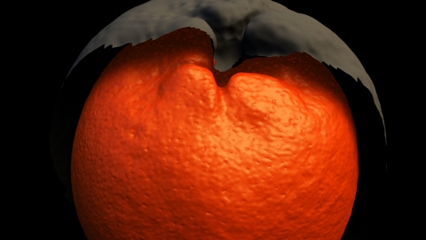
Making an Orange Shader, Shader Exercises

Intro
__________________________________________________________

I'll be making a procedural orange shader, that looks good at closeups. So this is an exercise in procedural noise layering. The main take away here,
  • identifying noise layers/general analysis
  • chaining bump maps
I always start out with references, so here are some,


source

This pretty much has all the properties an orange in detail. I want an extremely red orange, so I will push it even further than the above image.

I can quickly outline some bump noise patterns I can see here,
  • high frequency, ~0.4mm to 0.8mm, these are the cellular bumps and color at extreme close up
  • medium frequency, there are some dimples ~0.5mm to 1mm, but their profile is such that its more visible
  • low frequency, large scale knobbiness of the orange skin, some browning skin patterns
Some notes on the color, sss, and reflection
  • high frequency leathery skin thats even more pronounced in SSS
  • high glossy specularity with color at the end of the falloff
  • to determine the average SSS, look at the light side to dark side fall off. Even 
Bump
__________________________________________________________

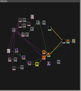
From my noise pattern outline, i quickly created 3 3d textures,
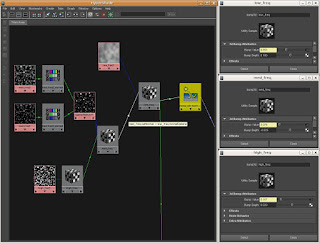
Bump Sub Tree
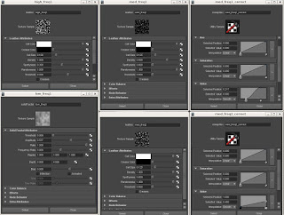
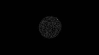
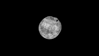
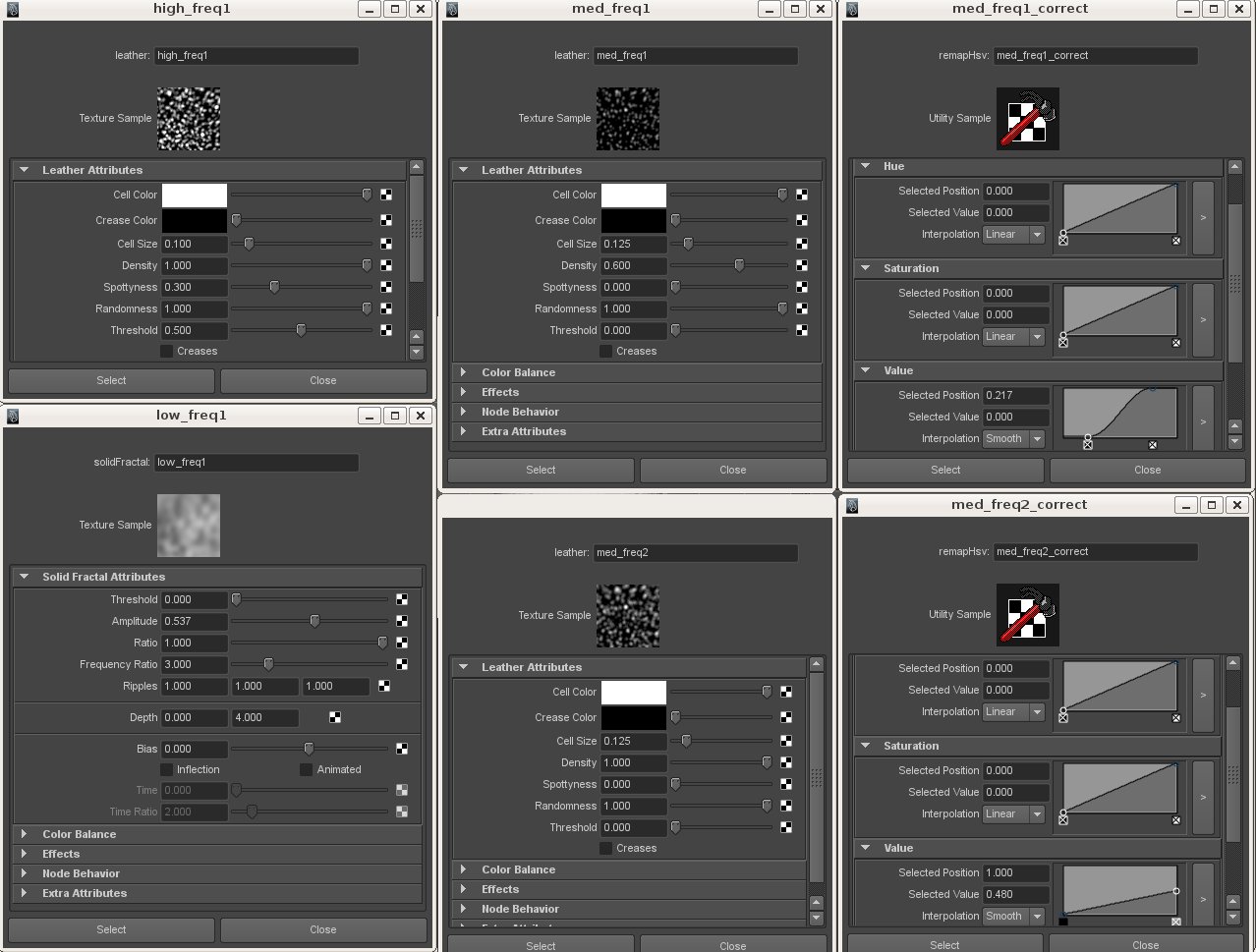
Low, Med, High Freq Map Settings
I used leather 3d texture maps for the high and med freqeuncy maps and a solid fractal 3d map for the low frequency map.
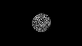

High Frequency Pattern
Med. Freq. Pattern 1

Med. Freq. value correct 1
Med. Freq. Pattern 2

Med. Freq. value correct 2

Low Frequency Pattern

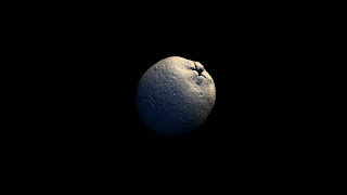
Final bump output
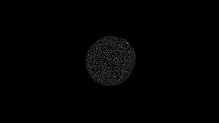
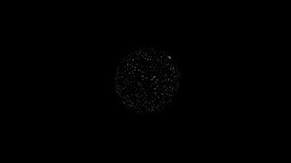
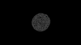
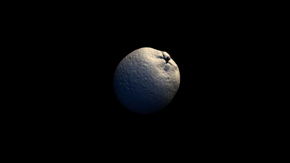
 I tweaked each individual bump pattern separately, determining that the high frequency patterns are small bump, while the medium frequency pattern are sharp holes, and the low frequency patterns are bumps as well. The geometry provided have built in low frequency noise as well. I chained each bumps' outnormal to the next bumps' normal camera to achieve the final bump output.


Diffuse & SSS
__________________________________________________________
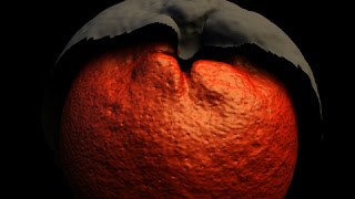

diffuse, spec, bump

I''ll work on the diffuse and sss at the same time, but first, I duplicated  the orange and scaled it up a little.
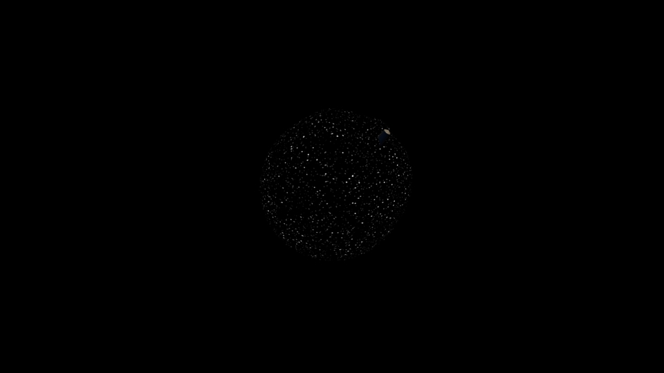
The reason being, I need to take a look at the SSS falloff, and for that I need to see how far the SSS penetrates into the shadow side of the orange. Don't worry about how the bump looks so strange, after adding SSS the high contrast washes out. 
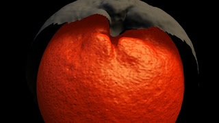
2.0 epidermal radius
For the above render, the epidermal radius is set at 2.0, which washes out any shadows, so i'll set it down to 0.2.
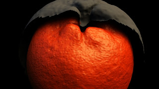
0.2 epidermal radius
This gives the shadow a softer edge and the light penetration is consistent with my reference. 
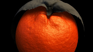
8.0 subdermal radius
The subdermal scatter looks like what I want to achieve, albeit not as intense as I am showing it here. If you shine a flash light, hold it close to the orange, you will discover that at high intensities, the light travels quite far inside the meat, and the skin has these little holes that light penetrates in and out of. Or the holes might not be holes but variations in the thickness of the orange peel. 
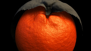
2.0 subdermal radius
Looks about the same, still too far inside the shadows
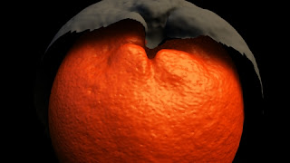
1.0 subdermal radius
Now, for the diffuse color, using a ramp with its built in HSV noise is good enough if the UV seams are hidden well enough. However, the models provided, and a lot of the times, UVs are an afterthought. As a shader artists, 3d procedural textures, custom coded or procedural texture trees(hypershade, slim, mental mill) are preferred.
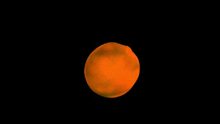
diffuse on surface shader
Final Shading Tree
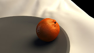
Final Render